


General knowledge of filtration technology
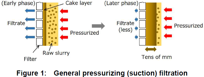
Filtration is an operation used to separate a slurry*1) into solid and liquid by a filtering medium (filter) *2). Filtration is proceeded by pressurizing a filter surface or applying suction from the opposite side of the filter. Particles are captured by the cake layer (particle layer) that is formed on the filter surface, and a clear filtrate (liquid) is separated. Filtration is an important operation in a wide range of fields, such as the chemical, food, and materials industries.
In a general pressurizing (suction) filtration machine, the thickness of the cake layer formed on the filter surface increases as the filtration progresses, as shown in Fig. 1. In this case, the resistance of the liquid passing through the cake layer increases and the filtration rate drops sharply. To restore the reduced filtration rate, it is necessary to disassemble the equipment and scrape out/off the cake layer using a scraper.
*1) Suspended solid particles in liquid
*2) Filter cloth, filter paper, wire mesh and membranes are widely used.
Filtration by Rotary Filter and Ceramic Rotary Filter
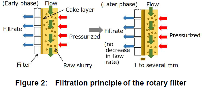
With general filtration, the cake layer gradually deposits, and the filtration rate drops consequently. The Rotary Filter (RF) and Ceramic Rotary Filter (CRF) suppress the deposition of a cake layer and maintain a high filtration rate for long periods by using a unique method of intense agitation in the vicinity of the filter media.
(1) Principle
As shown in Fig. 2, the liquid flows at a high speed in the direction parallel to the filter medium by the rotation of the agitating plates, which keeps the thickness of the cake layer on the filter thin and constant. This method enables a minimal cake layer to be maintained, i.e., with a thickness of approximately 1 to several millimeters for long periods, which allows for a stable high-speed filtration.
(2) Structure
■ Rotary Filter (RF)
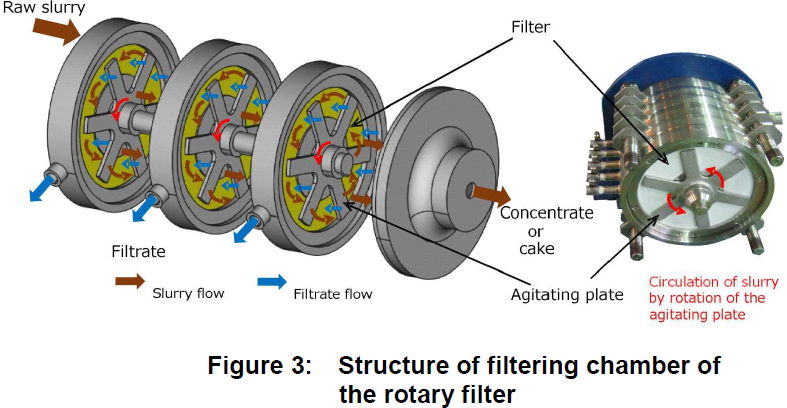
The RF is suitable for capturing fine particles from submicron sizes up to 100 μm. Figure 3 shows structure of the RF. The filtration and the agitating plates are alternately placed at narrow intervals in the filtering chamber with a completely sealed structure, and the agitating plates rotate continuously during the filtering operation. The raw slurry is pressurized and fed from one side of the filtering chamber. The slurry is filtered and concentrated while moving through the filtering chambers, after then it is discharged as a concentrate or a pasty cake from the discharge valve on the other side of the filtering chamber.
■ Ceramic Rotary Filter (CRF)
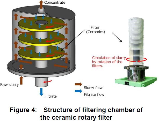
The CRF is suitable for capturing ultrafine particles from nanometer to submicron sizes. Figure 4 shows the structures of the apparatus and the ceramic filter. In the filtering chamber that is completely sealed, hollow disk-shaped ceramic filter plates are mounted to the rotating shaft and rotate at a high speed during the filtering operation. The raw slurry is pressurized and fed from one side of the filtering chamber. The filtrate, which is filtered by the ceramic filter, passes through the hollow shaft and is discharged to the outside.
(3) Features and benefits
■ Rotary Filter (RF)
1. Realizing high-rate long-time filtration of particles up to submicron sizes
A high filtration rate is maintained while filtering a slurry with particles of several micron to submicron sizes for several days
or months, since the turbulent flow along the filter surface keeps the thickness of the cake layer thin.
2. Ideal for rinsing and removing dissolved salts in the slurry
Impurities that are dissolved in a slurry, such as chlorine and alkaline ions, are removed at a higher rate by the RF than
other processes, as a high filtration rate is maintained. In addition, the solid particles are rinsed in a dispersed condition that
adequate for slurry circulation, so that a high rinsing efficiency is achieved in a short period of time.
3. Cake with consistent concentration and fluidity is discharged continuously
Disassembling the filtering chamber to discharge the cake is not required. It is possible to keep all the process stages under
completely sealed conditions. The cake is fluid, resulting in a good handling during post-processing (e.g. drying).
■ Ceramic Rotary Filter (CRF)
1. Nanoparticles are captured, and a clear filtrate is obtained
A microporous ceramic filter with a pore size ranging from 7 nm to 2 μm is available to capture nanoparticles completely,
which is difficult with conventional technologies. This enables the continuous collection of a clear filtrate.
| Pore diameter |
2.0μm | 0.5μm | 0.2μm | 60nm | 30nm | 7nm |
|---|---|---|---|---|---|---|
| Material | Al2O3 | Al2O3 | Al2O3 | Al2O3 ZrO2 | TiO2 | MgAl2O4 |
2. The CRF is applicable to slurries that are easily clogged
The pore size of the ceramic filter is much smaller than the particle size, thus filter clogging is prevented. The CRF is optimal
for particulate slurries that easily clog filter cloths or wire meshes of other processes, and it is also applicable to dilute slurries
that do not easily form a cake layer.
3. High-rate filtration of nanoparticle slurries while maintaining stable performance
The ceramic filter rotates at a high speed to maintain a thin and stable cake layer. The CRF preforms much higher filtration
rate with a slurry that is hard to be filtered or very low in the filtering rate with other ordinary filtering processes does. Thus,
the CRF realizes the stable filtration rate with even slurries with nanoparticles.
■ Common features of RFs and CRFs
1. Better quality control and lower production costs by filtering process automating
Quality control is easily performed by the automatic control of the RF/CRF processes, in which the degrees of cleanliness
and thickness of the slurry are detected and used for controlling. After filtration, the machine can be back-washed in an
automatic mode. This helps to increase the yield, reduce the required manpower, and reduce the production costs.
2. A completely closed filtering process allowing clean working environments
There is no need to disassemble the filtering chamber to maintain performance of the filtration, recover the processed
products, or clean the machine. Thus, it is possible to keep all the process stages under completely sealed conditions. The
closed processing results in clean working environments, fewer cleaning process steps, and reduced production costs. In
addition, it prevents slurry scattering, odor generation, and exposure to hazardous substances.
Applications of RFs and CRFs
Figure 5 shows the process flow of the rinsing, concentration, or dewatering operation performed by the RF and CRF. These operations are performed in combinations. For example, the slurry rinsed at the first stage is also concentrated to be recovered.
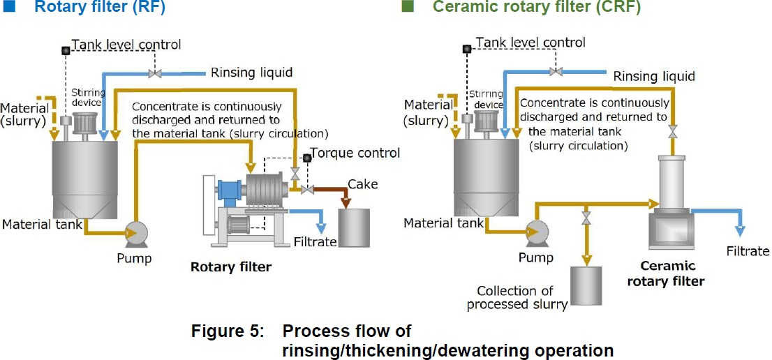
(1) Rinsing operation
In material processing procedures, a slurry may contain several chemicals and agents for promotion of reactions or nuclei formation. Some slurry contains impurities that dissolve in the liquid of the slurry. To improve the qualities of the final products, it is very important to remove the impurities. Hence, filtration is widely applied to rinse slurry to remove the dissolved impurities.
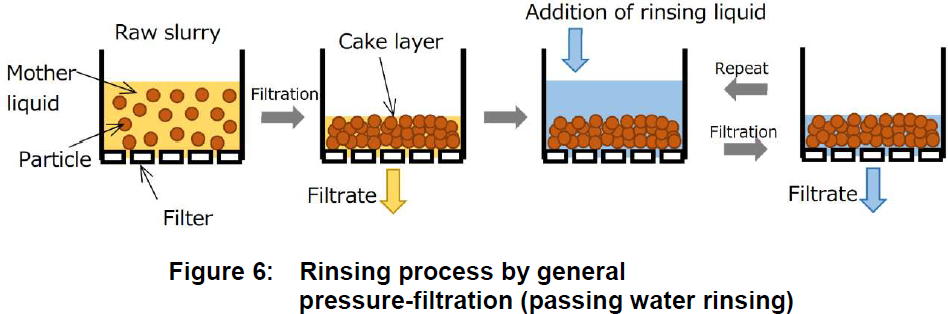
For general pressuring filtering machines, the raw slurry is filtered to form a cake layer on the filter surface, as shown in Fig.
6. The impurities are subsequently rinsed by the rinsing liquid flowing onto the cake layer. However, since the rinsing is
performed in a state where particles are consolidated, the particles are not completely washed by one practice. Furthermore,
the filtration rate of the ordinary filtering processes is low due to the thick cake layer, and time required for rinsing is generally
long.
The RF and CRF perform the rinsing process during filtrating a slurry by mean of circulating the slurry in a combination of a
filtering machine and a tank. The slurry is dehydrated by filtering at the first stage and then is diluted in the tank by adding
rinsing water. The dissolved salt flows out through the cake and the filter, and its concentration decreases as rinsing water
to compensate for the discharged liquid.
Rinsing is performed on particles in a dispersed state, and thus, rinsing progresses uniformly. Furthermore, the rinsing
process is performed in short time because of the high filtration rate.
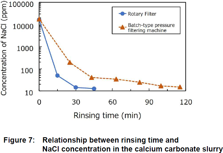
Figure 7 shows an example of rinsing a slurry of calcium carbonate with sodium chloride. Time required to reduce
concentration of sodium chloride by the RF is 1/3 the time required for general batch-type filtering machines.
Examples of other rinsing practice are as follows:
| Industry classification |
Solid Material | Impurities | Degree of cleanliness |
|---|---|---|---|
| Magnetic material |
Fe2O3 | Cl | Cl- 10% → <0.1% |
| -〃- | -〃- | H2SO4 | pH <1 → 4.5 |
| -〃- | -〃- | NaOH | pH 12.4 → <9 |
| Fine ceramics | ZrO2 | Cl | Cl- 3.4% → <0.5% |
| Optical material | SiO2 | Cl | Cl- 1000ppm → <10ppm |
| Building material |
Ca3(PO4)2 | NH4Cl | pH 9 → 7.6 |
| Photocatalyst | TiO2 | NH4Cl | Cl- 32g/L → <1g/L |
| Chemical products |
Al(OH)3 | NH4Cl | Cl- 2% → 0.01% |
| Electrolytic foil | Cu | HCl | pH 0.78 → 4 |
| Paint | Pigment | NaCl | Cl- 10% → 2% |
(2) Thickening/dewatering operation
It is necessary to disassemble the filtering chamber after dewatering the slurry and scrape the cake out for general pressure
filtering machines. On the other hand, the RF filters the raw slurry and accumulate the cake on the filter inside a sealed
chamber. A motor torque sensor detects state of the solids accumulated on the filter, and the cake discharge valve acts to
discharge the cake when the detected torque exceeds the preset value. With this automatic discharge mechanism, a cake
with a desired moisture content is recovered continuously.
As a slurry is filtered by the CRF in a circulating manner, concentration of solids in a liquid in the circulation tank increases
gradually.
For the RF and CRF, it is not necessary to disassemble the filtering chamber to collect the cake or thickened filtrate after
processing, and thus, the operation is performed under completely sealed conditions and automatically.
| Industry classification | Solid material | Solid concentration of the cake (mass%) |
|---|---|---|
| Magnetic material | Ferric oxide – Ferrite | 60–70 |
| Photocatalyst, MLCC | Titanium series | 40–60 |
| Fine ceramics | Ceramics | 30~70 |
| Building material, food additive |
Calcium series | 25–50 |
| Mining and manufacturing |
Magnesium series | 25–30 |
| Grinding agent, fireretarding material |
Aluminum series | 15–20 |
| Paint | Pigments – Colorant | 25–30 |
| Nuclear paraphernalia | Activated carbon | 35–40 |
| Paint, coating agent | Resin | 20–25 |
| Secondary battery | Positive-electrode materials |
60–70 |
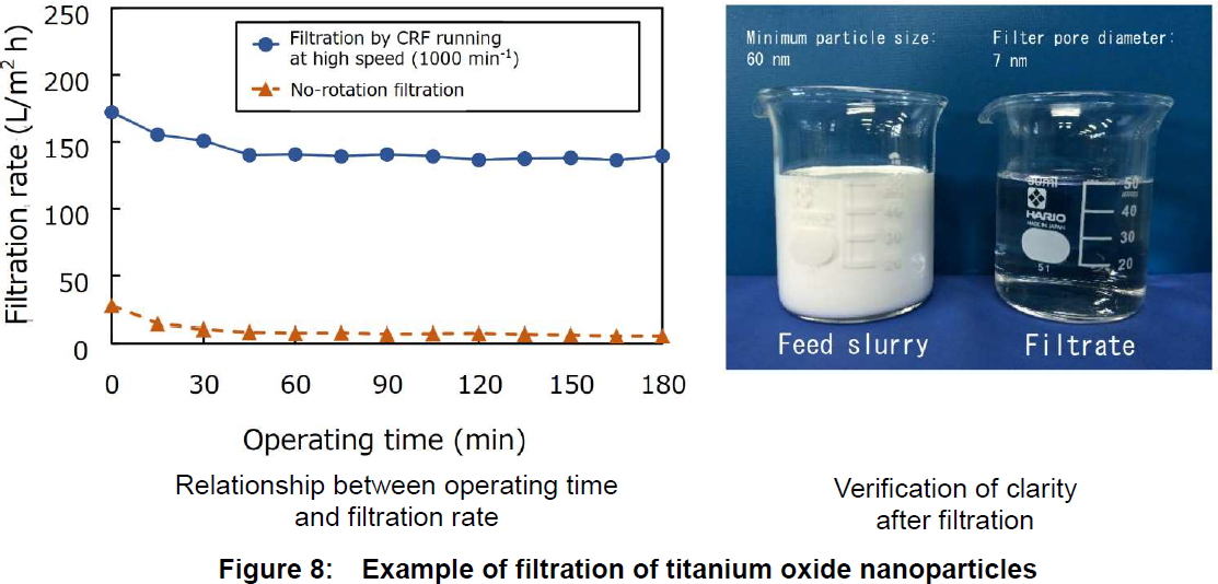
(3) Filtration of nanoparticles
Ceramic filters of the CRF capture nanoparticles, which is difficult for them to be separated from slurry with conventional
filtration methods using filter cloths.
Figure 8 shows an example of the filtration of a nano-sized titanium oxide slurry.
The filtration rate of the filters rotating at 1000 RPM is about 20 times that of the filters without the filter rotation, and
nanoparticles were completely captured the ceramic filter with ultramicroscopic pores .
Specifications and application examples
| Model | Rotary Filter [ RF ] |
Ceramic Rotary Filter [ CRF ] |
|---|---|---|
| Applicable particles |
Fine particles | Ultrafine particles |
| Size | Submicron to 100 μm | Nano to submicron |
| Process | Rinsing, thickening, and dewatering | Rinsing and thickening |
| Filter media | Filter cloth | Ceramic filter |
| Filtration rate※1) | 200–2000 L/m2hr | 20–500 L/m2hr |
| Standard material of filtering chamber※2) |
SUS304 | SUS304 |
| Applications | 1.Electronic component materials (e.g., MLCC and magnetic materials) 2.Secondary battery materials 3.Metal hydroxides, oxides 4.Pigments (e.g., toners and color-filter resists) 5.Cosmetic materials (e.g., calcium carbonate and titanium oxide) 6.Metal recycling 7.Wastewater treatment in nuclear Facilities |
1.Functional materials (inorganic nanoparticles) 2.Removal of solids from the coolant 3.Latex 4.Foods (removal of sediment, e.g., from wine and beer) |
*1) Filtration rate is the filtrate discharge amount per filtration area.
*2)Filtering chamber can be made of materials such as SUS304, SUS316, SUS316L, titanium, and polypropylene (acid-proof type), depending on the properties of the slurry.
Lineup
| Type | Filtration area (m2) |
Main motor (kW) |
Length (m) |
Width (m) |
Height (m) |
Approx. weight (kg) |
|---|---|---|---|---|---|---|
| RF-02 | 0.18 | 3.7 | 0.95 | 0.60 | 0.95 | 550 |
| RF-1 | 1 | 5.5-7.5 | 1.50 | 0.80 | 1.20 | 750 |
| RF-2.5 | 2.5 | 11-15 | 1.70 | 0.90 | 1.40 | 1200 |
| RF-5 | 5 | 22-30 | 2.00 | 1.30 | 1.60 | 1700 |
| RF-10 | 10 | 37-45 | 3.20 | 2.00 | 1.40 | 3900 |
| RF-20 | 20 | 45-55 | 3.50 | 2.30 | 1.95 | 5800 |
| RF-30 | 30 | 55-90 | 3.90 | 2.40 | 2.10 | 8000 |
| Type | Filtration area (m2) |
Main motor (kW) |
Length (m) |
Width (m) |
Height (m) |
Approx. weight (kg) |
|---|---|---|---|---|---|---|
| CRF-0 | 0.03 | 2.2-3.7 | 1.0 | 0.6 | 1.2 | 500 |
| CRF-1 | 1 | 3.7-5.5 | 1.5 | 0.8 | 1.2 | 650 |
| CRF-2 | 2 | 3.7-5.5 | 1.5 | 0.8 | 1.5 | 750 |
| CRF-5 | 5 | 7.5-11 | 1.5 | 0.8 | 2.2 | 1200 |
(References)
1. M. Ikyo, “Introduction of nanoparticle dispersing device developed utilizing experience of filtration and centrifugation
and application example,” Filtration and separation symposium 2009, Vol. 101-108 (2009)
2. Y. Tokunaga, M. Inkyo, “Development of super-precision filtering machine Ceramic Rotary Filter (CRF),” Filtration and
separation symposium 2009, Vol. 139-142 (2009)
3. Y. Tokunaga, “Application of closed-type automatic continuous pressure filtering machine Rotary Filter,” Filtration and
separation symposium 2013, Vol. 52-56 (2013)
4. Y. Tokunaga et al, “Proper method of filter scale-up and success examples,” Chapter 5, 1-6 (2014)